Nota Técnica #32
Abril de 2018
Por Laura Oriol
Some models cover large and complex systems that may require different levels of simulation. Smaller subareas typically require detailed simulation approaches, such as microscopic simulation, whereas it is far faster to use simplified models, such as mesoscopic simulation, to model the wider areas.
On the basis that microscopic and mesoscopic models are never going to produce the same results, it is important to get a good match in behavior wherever possible. Assuming that a microsimulation approach provides more accurate outcomes, in some circumstances it is necessary to calibrate the default meso parameters to achieve analogous results in both models.
The following guidelines aim to provide an insight into how in meso existing parameters can be altered to match the microscopic model behavior in specific situations.
Lane Changing in Weaving Areas
Weaving areas or sections (Figure 1) involve the crossing of entry and exit traffic traveling in the same direction over a short distance.
Storage Capacity in Intersections
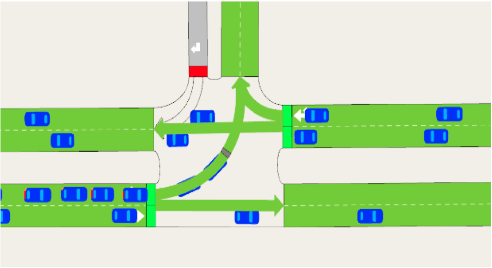
In certain cases, it may be necessary to implement stop lines in turnings to increase their capacity or to reproduce the actual behavior of drivers. This is the case in the following intersection (Figure 3) where vehicles can turn left but must give way to vehicles on the main road.
Example
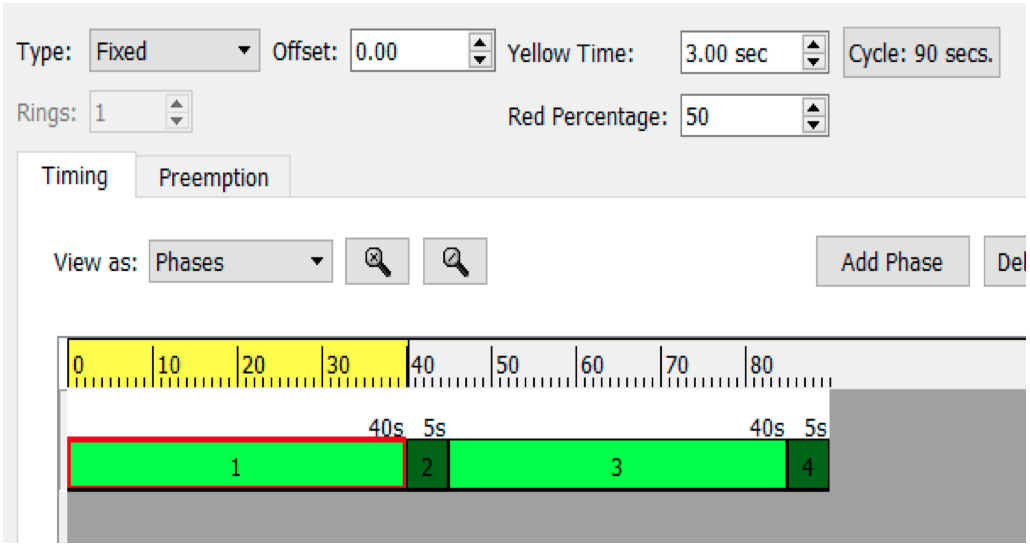
If we take the previous intersection and the following control plan:

– Total Green Time = Green Time + Red Percentage · Yellow Time = 40s + 0.5·3s = 41.5s
– Total Green Time / Number of vehicles = 41.5s/2vehicles = 20.75s/veh
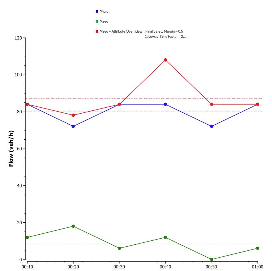
Each vehicle has 20.75s to take the turn. The general idea is to set a very low Final Safety Margin (See Figure 6) to ensure that the vehicle goes through and a Give Way Time Factor that corresponds to the desired maximum time the vehicle will wait (20.75s). The default Initial Safety Margin is 10 seconds, so for this example the Give Way Time Factor must be set to 2.1 (20.75s/10s=2.1).
By following this procedure, you should achieve the desired turning flows (Figure 7).


